Archiv der Kategorie: electronics

micro benchtop power supply (DP30V3A)

tldr

  1. notched box online designer
  2. convert to dxf online
  3.  some CAD work
  4. lasercutting
  5. modding the power supply to 35V
  6. assembly

long version

Danny showed me the  DP30V3A – thus emerged the idea to „briefly“ build a tiny  benchtop power supply that is powered directly by a wall outlet.

img_20160925_203220

As I didn’t have access to a lasercutter for a while this project just collected dust.

Now there is even better adjustable power supply successors – the DP30V5ADP50V2A or even the DP50V5A module.

I opted for the 36V version of the Qianson WX-DC2416 switching power supply as power source for the DP30V3A since it was the smallest 230V -> 36V power supply with enough amperage I could find at the time.

It does require a quick mod though because the  DP30V3A can only handle 35V.

img_20160924_213634

As you can see I placed a 47k multi-turn precision potentiometer in place of the R11 resistor (original value 20k).

This R11 resistor is part of a voltage divider that adjusts the output voltage.

driving a brushless motor with a microcontroller + L6234d


parts:

  • L6234 Three phase motor driver (essentially 3 half bridges) from the drotek.fr guys (recommended)
  • teensy 3.0 (yeah, overkill – but it was at hand) – btw: Paul rocks – as do his microcontrollers and libraries!
  • GBM4108-120T brushless motor (lying around for a future gimbal build)

code:

  • github
  • what it boils down to
     analogWrite(phase1Pin, sin_tbl[phase]);
     analogWrite(phase3Pin, sin_tbl[uint8_t(phase+85)]);
     analogWrite(phase2Pin, sin_tbl[uint8_t(phase+171)]);

pictures:

K2 Kickboard ev mod – analog to pdm controller

After I avoided programming my own microcontroller to get the thing rolling in as little time as possible (sidetracking kills a lot of drive) – I finally decided it was time to take it on.

Actually the realisation that the cheap servo tester assumes the poti position when powering up as middle position convinced me that it was necessary to write my own speed controller – since I can’t (or at least not realiably/comfortably) use the braking functionality of the alien power sytem esc.

Also this way I can – or at least I can try to – write my own soft-start routine so people don’t fall off the back.

@phrewfuf encouraged me to program the arduino nano I tucked in a box some months back for when the time was right 😉
Since he didn’t send me the code I just set down myself today and took the first steps.

Also I had to wildlarize the freaking busted poti I pulled out of a part drawer. If you’re  not familiar with the term:

„widlarize“ (invented by Bob Widlar): You take the bad component to the anvil part of the vice and beat it with a hammer। It will make you feel so good, for no damaged parts will appear in your latest application।

It sucks so hard wasting time and money with  broken components that I consider not reusing old parts – or at least not the parts lying around shackspace 😉

Here is already another poti hooked up to an analogue pin linked to the pin the servo is connected to:

#include <Servo.h>

//onboard led
int ledPin = 13;

//servo pin
int escPin = 3;  // servo signal connected to digital pin 3
Servo escServo;

int potiPin = 7; // potentiometer wiper (middle terminal) connected to analog pin 3
int potiVal = 0;     // variable to store the value read from the poti

void setup()
{
  pinMode(ledPin, HIGH);
  escServo.attach(escPin);
  //initial Servo Position
  escServo.write(0);
}

void loop()
{

  potiVal = analogRead(potiPin);    // read the input pin
  potiVal = map (potiVal, 0, 1023, 0, 180); //convert input range to servo range
  escServo.write(potiVal);

}

Result:

Next up I need want to get interrupts working.

K2 Kick Pro Kickboard mod with 3kw outrunner

I still have a backlock of the past two years – but with this project I actually did quite a nice job documenting it.

Best of all it’s

and you can get all the CAD files on github.

Now to the build. Since I’m not big on baking cookies for Christmas – I invested my time in a project I was thinking about doing for some time: Building an electrified kickboard. This is the result:

The ingredients are:

from the shop:

from the parts bin:

cooking:

  • a day of CAD work
  • a day of milling aluminum (and some minutes on a lathe)
  • a day putting it all together + some soldering

I took the easy way – just to get the thing functioning (let’s deal with a microcontroller + programming later – if I need to) – and just soldered an extension cord + push potentiometer to the servo tester.

Also I desoldered everything unneeded from the servotester – but the better/faster method would have been just to cut the unneeded parts with pliers.

Next I sat down at the computer and let my ideas form in CAD. (This is the 3rd iteration)

First milled parts taking shape (these are the right and left axle mounts)


There is a mechanism for tensioning the belt by sliding the motor mount.


It looks nice enough … doesn’t hold up to the torque though – and so I had to redesign it later.


The process of milling the back plate:

The program used (XpertMILL):

and the finished part next to the original one:


The „gas pedal“ fitted to the handle:

A video of the first motor test:

As a quick hack to get moving I made a big Y-cable to fit the batteries into the left and right trouser pocket with a really long cable down to the esc.

A test ride (video suffering from vvs)

She is having trouble keeping the front wheels on the ground during acceleration 😉

The process of building the new battery pack from used Makita battery packs with 18650 cells:

balancing the Frankenstein pack:

Lasercut insulator rings and leads soldered across the top (3p configuration)

Soldered into a 7s 3p pack:

shrink wrapped:

Fitted to the kickboard:

For safety I should still put a 2mm aluminum sheet under the cells.

Some links and data:

Quite useful for calculating the drive train is http://smarthost.maedler.de/maedlertools/maedler.html

The data:

The measured no load rpm of the motor is 1295 which according to 4.2V*6*170rpm/V *12 / 40 = 1285 rpm … sounds legit.

This yields in 1295U/min * 11cm * pi / 100 cm/m / 1000 m/km * 60 min/h = 26.85 km/h @ no-load … or estimated 26.85 km/h * 0.8 = 21.5 km/h – theoretical.

The top speed – measured – is 22km/h with 6S, or 26km/h with 7S.

Energy consumption is about 13Wh/km (gunning it).

The battery pack holds 3.7V*3*7*2.5Ah=194.25Wh nominal … but since these are used and abused cells from Makita power drills the actual value should be lower.

Theoretical range is therefore about 15km – the real range is yet to be tested.

Max load was 38A – that would be 1kw of power to the motor – with a 100kg person on it and I guess the limiting factor are the cells and worn down T5 belt that will be replaced with an AT5 belt and pulleys.

http://www.youtube.com/watch?v=Wa9pRsZ2JA4

OpenWrt -> Linksys wag160n_v1

Victory: one of my tiny white whales has been slain.

Flashing OpenWrt to your router is easy as pie – at least in some cases – in other only if you know what you’re doing and a suitable firmware file is available.
I have to admit it took me almost 2 years to get OpenWrt on my Linksys wag160n v1.
Today I conquered that tiny white whale of mine.

serial connection soldered

I bought the unit back in 2011 because it seemed like a good choice looking at the OpenWrt toh (supported hardware) – at the time.

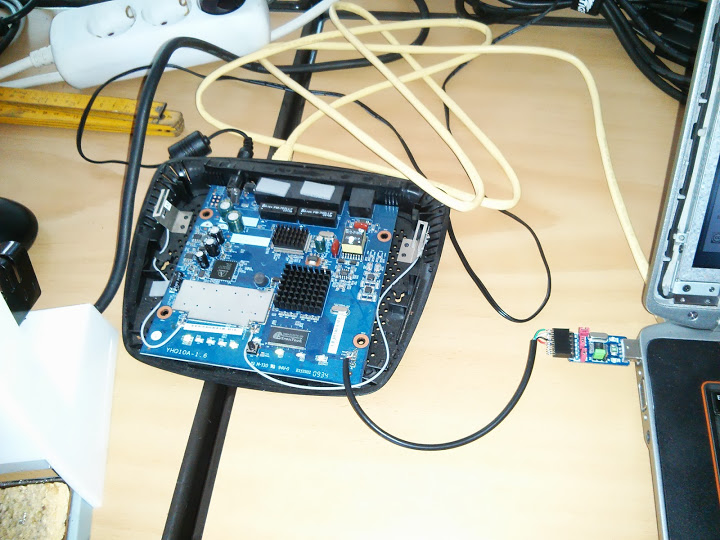
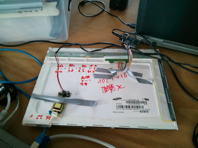
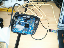
After I got it I quickly soldered the serial connector to the board and dumped the configuration data for the ath chip as described in the OpenWrt wiki.

After that it took me quite some time trying to build my own firmware – incorporating all the patches which should yield in a usable firwmare.

I got that done enduring some pain (a few days of forcing myself to patching files and compiling the firmware).

So there I was with the untested firmware file that still wouldn’t upload through the webinterface of my Linksys router.

Frustrated I threw the unit into it’s box and then some corner.

While moving the box hit the light of day again so I saw myself forced to either conquer the box or throw it in the trash.

Today I managed to get it done – and here is how that works:

You need to get a tftp server up and running (I’m running some Ubuntu).

sudo apt-get install tftpd-hpa tftp

Be sure to test the setup – put some file in /var/lib/tftpboot  e.g.

sudo sh -c 'echo "hallo" > /var/lib/tftpboot/test'

tftp localhost
 get test
 Received 7 bytes in 0.0 seconds

So now you’re sure your tftp server works.

You can get the firmware for the wag160n v1 (Attitude Adjustment, r34073) here which is built by Virus or try the related wag160n_v1 forum thread.

Copy your downloaded/built openwrt image to to /var/lib/tftpboot


sudo cp openwrt-WAG160Nv1-squashfs-cfe-attitude-adjustment-beta-2.bin /var/lib/tftpboot/bcm963xx_fs_kernel

That file (and the name needs to be bcm963xx_fs_kernel because that’s the IP the wag160n CFE expects) is now waiting there to get pulled by your router.

Connect to your router with an ethernet cable.
Assign 192.168.1.100 to your box – because that’s what the wag160n will try pull the boot image from
(192.168.1.100 as gateway).

Next up you need to connect to the wag160n through telnet.

Setup minicom:

sudo minicom -s

-> serial port setup
A -> /dev/ttyUSB0 (or dev/ttyACM0 or whatever)
E -> E (115200) -> Q (8N1)
-> safe setup as dfl (or as <configuration_name>)

and connect with:

sudo minicom

or if you saved a named config with:


sudo minicom <configuration_name>

You should now be presented with a boot screen after plugging the power supply into the wag160n.

Wait for:

*** Press any key to stop auto run (1 seconds) ***

And press a key. Now you’re in CFE:

CFE>

press f.

Loading 192.168.1.100:bcm963xx_fs_kernel ...

Finished loading 2752516 bytes

Flashing root file system and kernel at 0xbfc10000: ............................

.
 *** Image flash done *** !
 Resetting board...

And that’s it. Next time you will be greeted by the openwrt screen.

</pre>
BusyBox v1.19.4 (2012-11-04 23:56:37 CET) built-in shell (ash)
Enter 'help' for a list of built-in commands.

_______ ________ __
 | |.-----.-----.-----.| | | |.----.| |_
 | - || _ | -__| || | | || _|| _|
 |_______|| __|_____|__|__||________||__| |____|
 |__| W I R E L E S S F R E E D O M
 -----------------------------------------------------
 ATTITUDE ADJUSTMENT (Attitude Adjustment, r34073)
 -----------------------------------------------------
 * 1/4 oz Vodka Pour all ingredients into mixing
 * 1/4 oz Gin tin with ice, strain into glass.
 * 1/4 oz Amaretto
 * 1/4 oz Triple sec
 * 1/4 oz Peach schnapps
 * 1/4 oz Sour mix
 * 1 splash Cranberry juice
 -----------------------------------------------------

Set a root password through telnet

passwd

and you’re good to connect through ssh.

Another option would be to hexedit the firmware file so you can load it through the Linksys firmware upgrade.
You would still need telnet to the box because ssh is only enabled after setting a root password with the above linked firmware file.

HDMI -> LVDS

„The only difference between screwing around and science is writing it down.“

Na gut. Oder zumindest kann ich später nachschauen wie es geht.

Ich habe mal nachgeschaut, wie man die sich mit der Zeit ansammelnden TFT Displays nutzen könnte und bin dabei u.a. auf den hdmi lvds converter von chalk-elec.com gestoßen.

HDMI_LVDS_back

HDMI_LVDS_front

Diesen habe ich vor ein paar Monaten bestellt – und spontan gestern Nacht verdrahtet.

Damit würde sich u.a. ein Display am Multicopter realisieren lassen. Die Zeit wird es zeigen ob ich die Idee weiterverfolgen und umsetzen werde.

Bestellt habe ich den Adapter als 1920×1080 24bit Version – die programmierten EDID-Informationen sind aber leider falsch – so taucht ein LGD  10″ 1280×800 Display im System auf:

hdmi_lvds_LGD10
$ xrandr
HDMI1 connected 1280x800+1600+0 (normal left inverted right x axis y axis) 217mm x 136mm
1280x800       60.0*+   40.0

Na gut - erst mal schnell an ein herumliegendes Display (Samsung LTN141X8-L02) angekabelt.
Relevant ist dabei eigentlich nur die richtigen Pins miteinander zu verbinden.
Pinout vom Display
Samsung_LTN141X8-L02_pinout
Pinout vom LVDS Adapter:
hdmi_lvds_pinout
Das kam dabei raus:
HDMI_LVDS_cables

Dell_HDMI_LVDS_Samsung_10

Joa, nicht so toll:

HDMI_LVDS_fail

Der Versuch einfach die richtige Auflösung "rauszupusten":

$ xrandr --addmode HDMI1 1024x768

$ xrandr
HDMI1 connected 1024x768+1600+0 (normal left inverted right x axis y axis) 217mm x 136mm
1280x800       60.0 +   40.0
1024x768       60.0*

hdmi_lvds_LGD10_addmode

bringt den Erfolg:

HDMI_LVDS_success

proof of concept: done
Der nächste Schritt wäre einen 27" IPS Monitor zu schlachten und das Experiment zu wiederholen.