I searched my photo albums for some pictures of robot stuff that I did the last years (robots being only one of many interests).


Prev
Next
How it all started (the robot uprise):

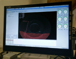
Retrofitting a Manutec R15 with modern motor drivers and LinuxCNC control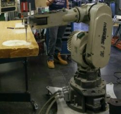

Project: Self balancing bot with manual PID
(derived from)
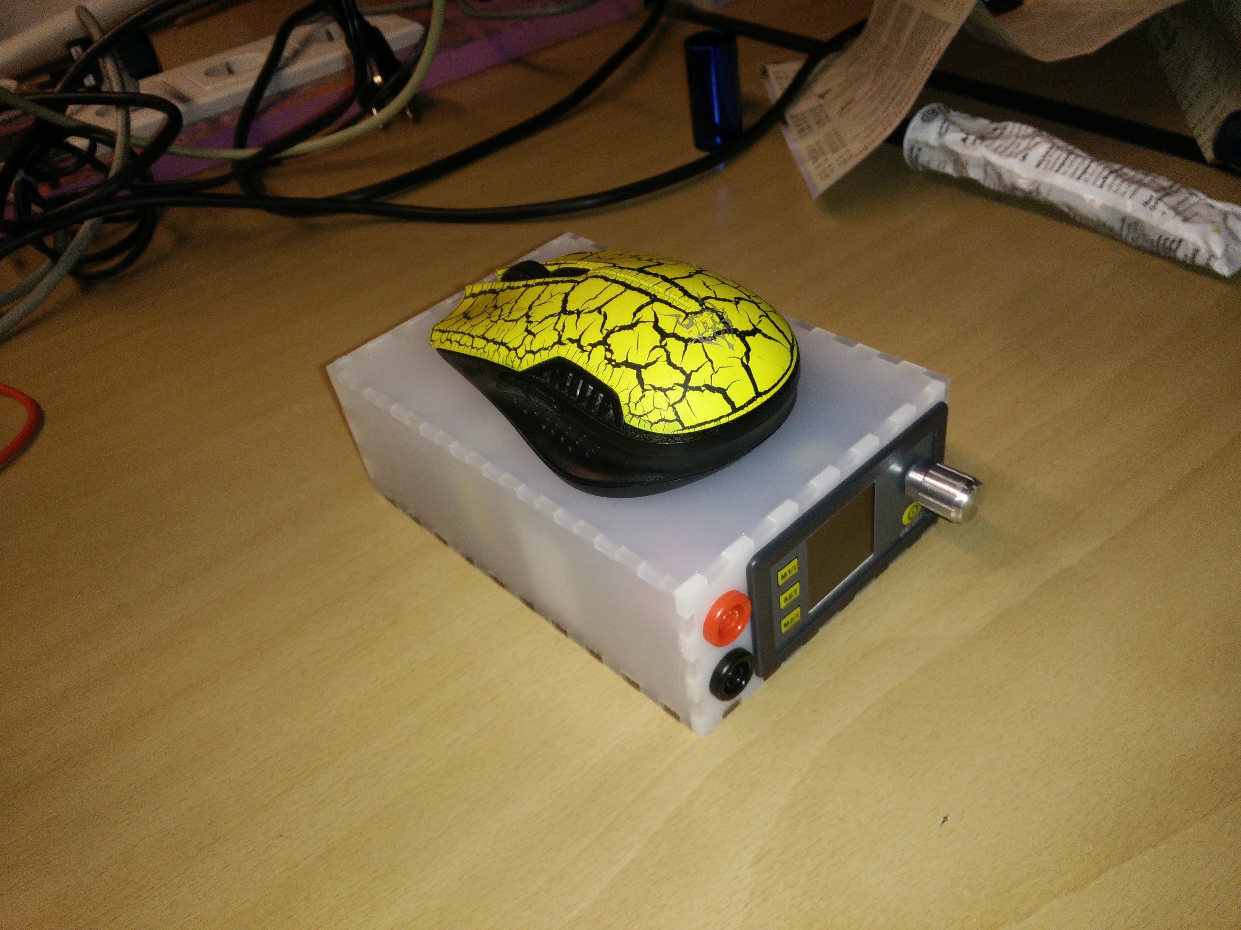
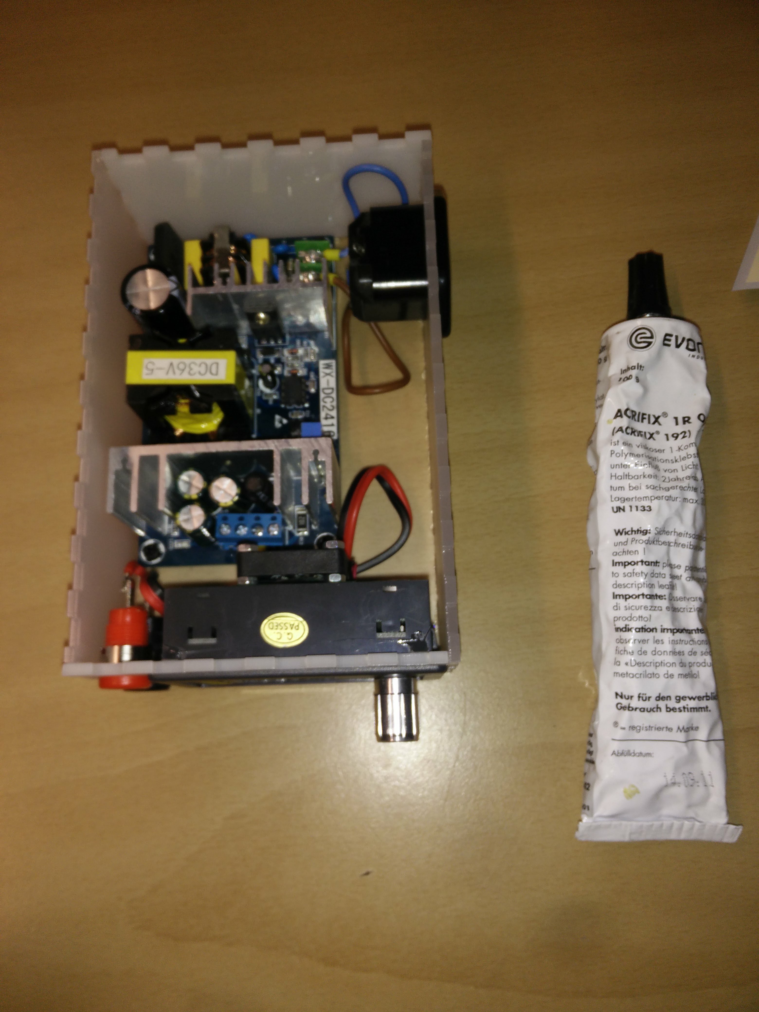
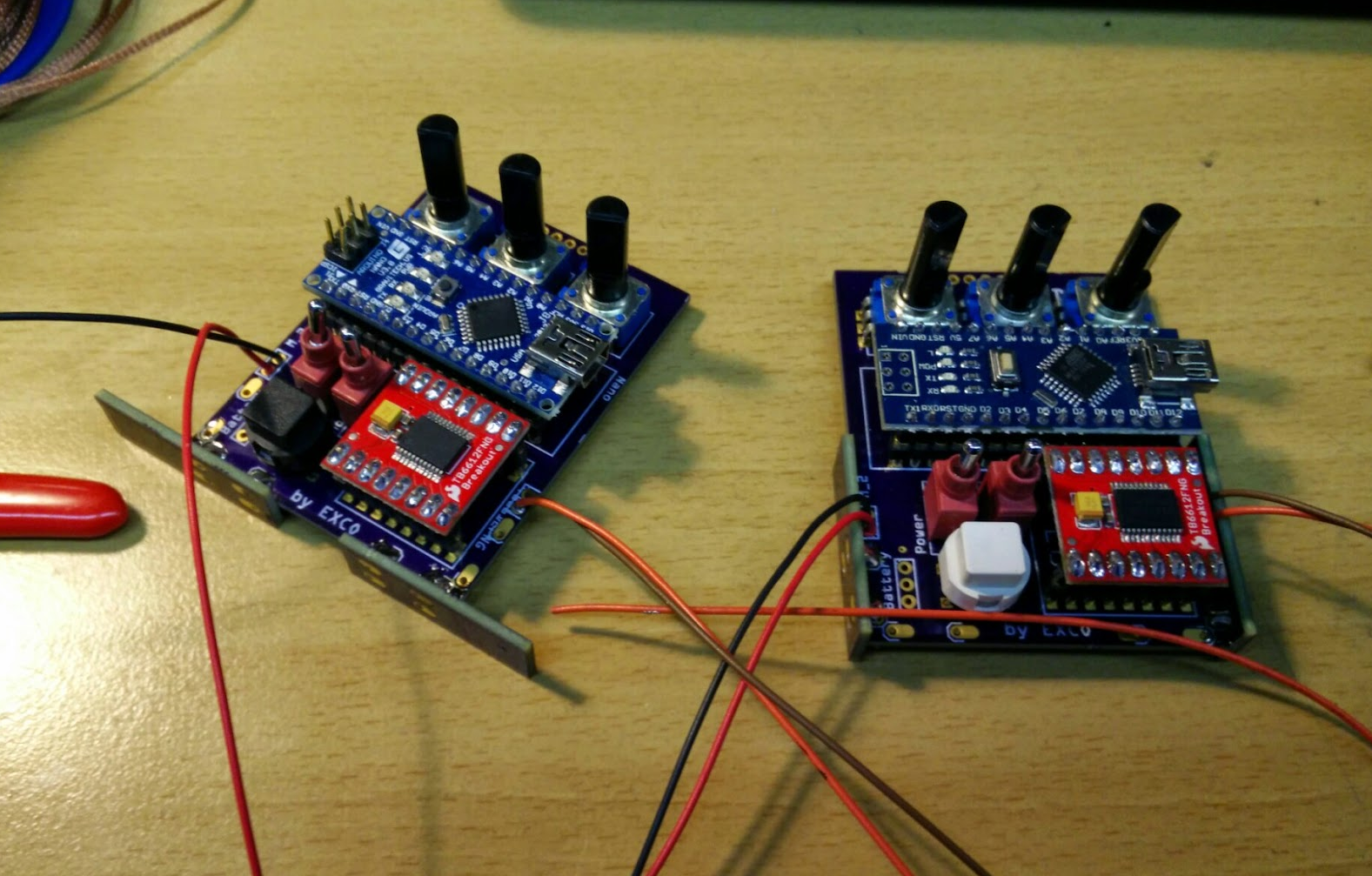
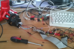
ugly prototype:
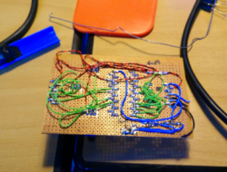
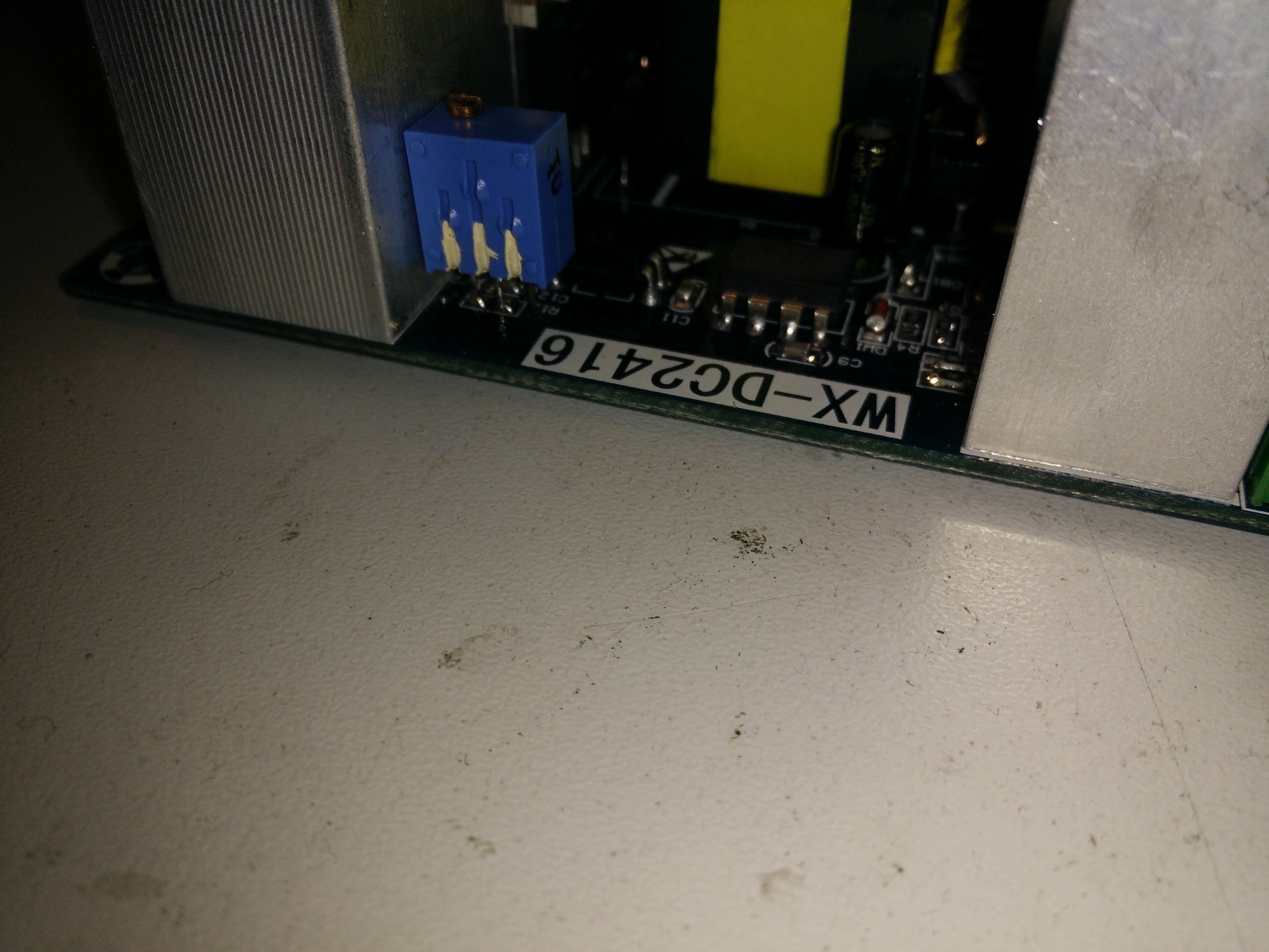
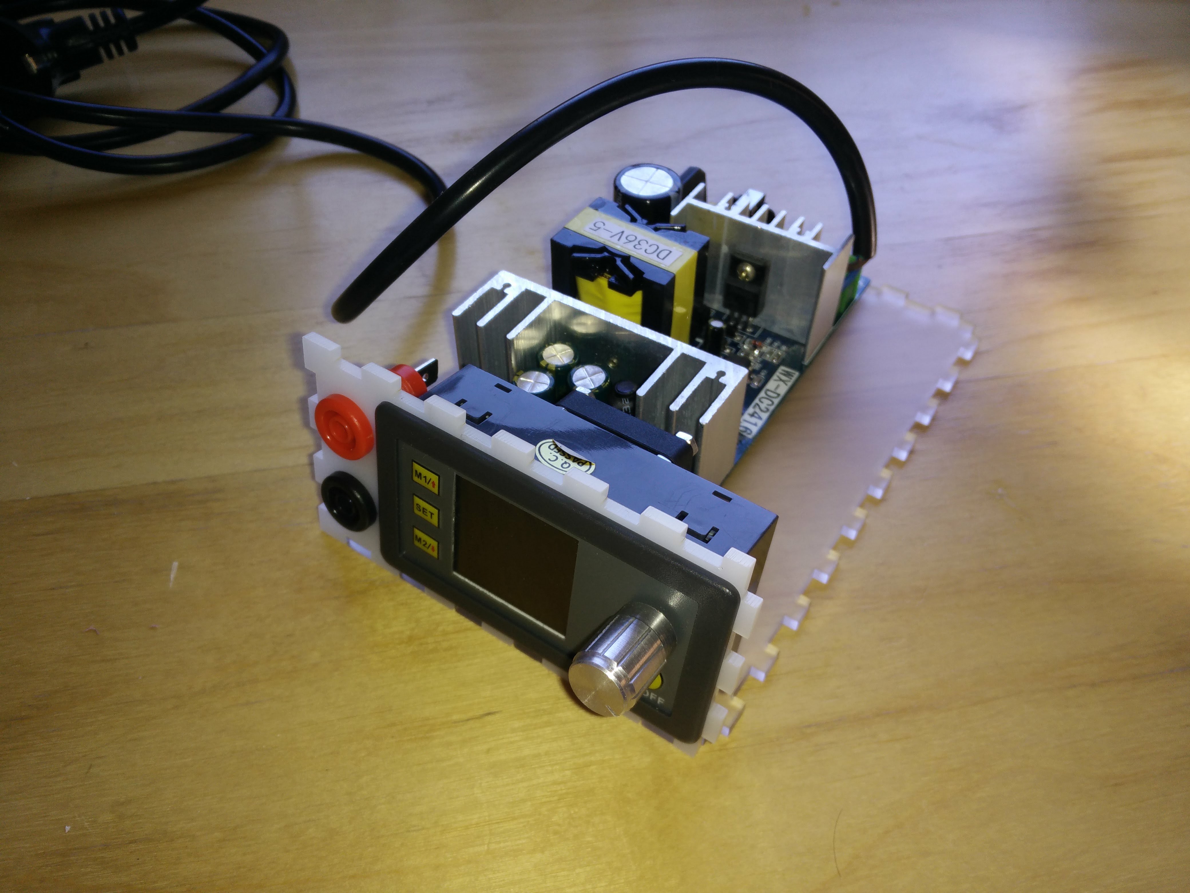
I’ll hopefully never do airwiring again – hint: invest the time layouting pcbs instead:
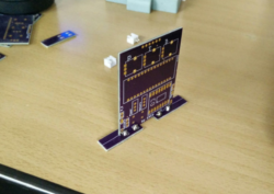
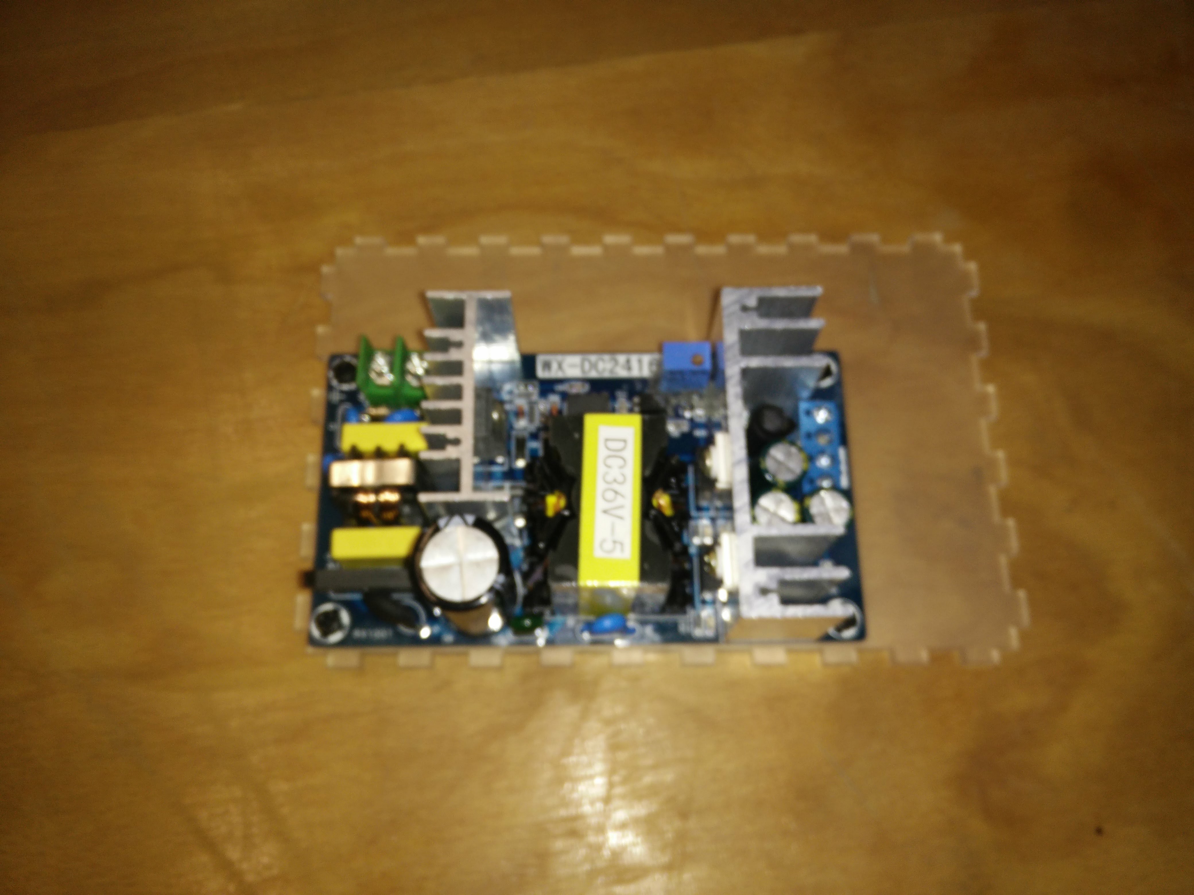
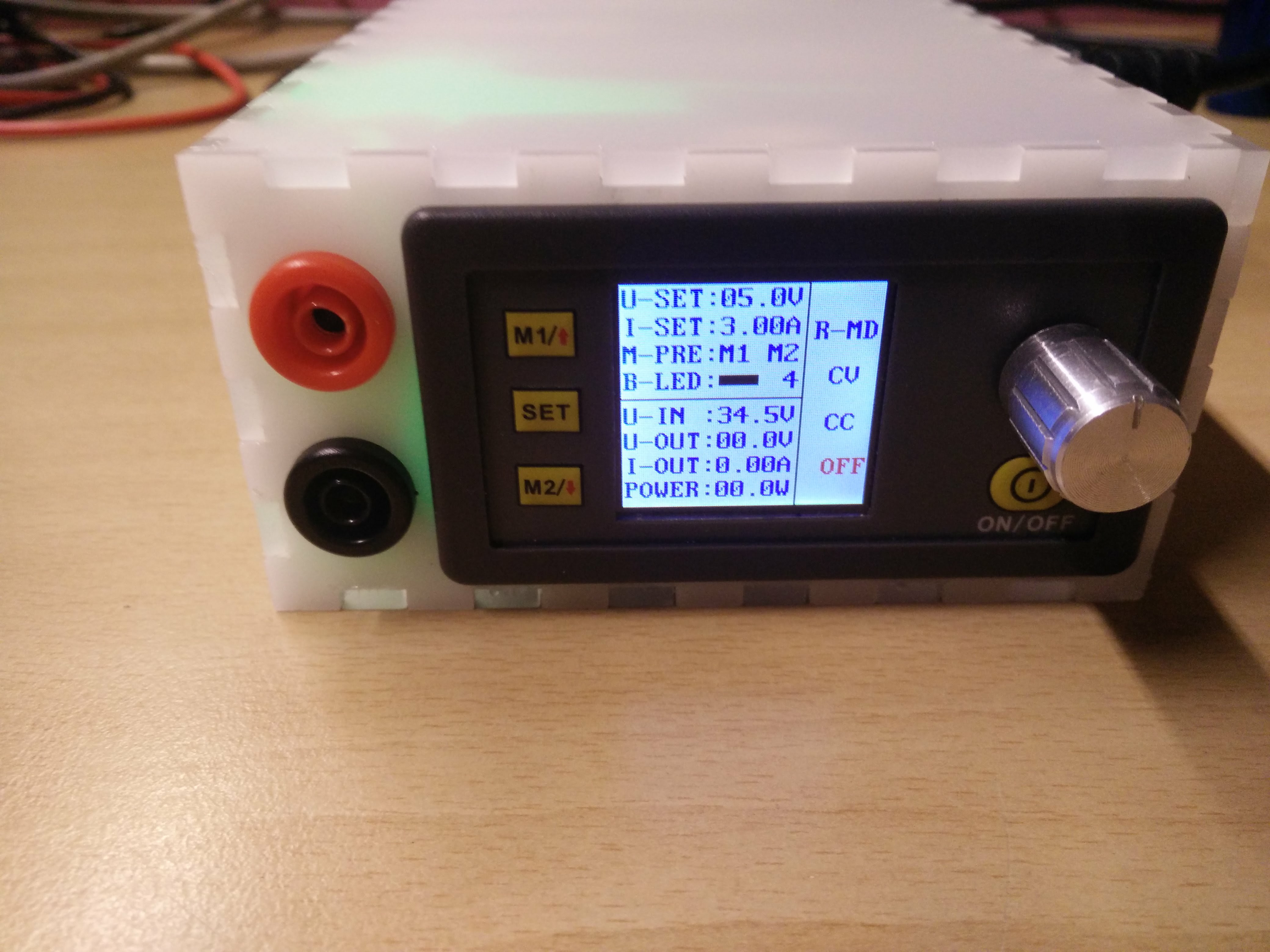
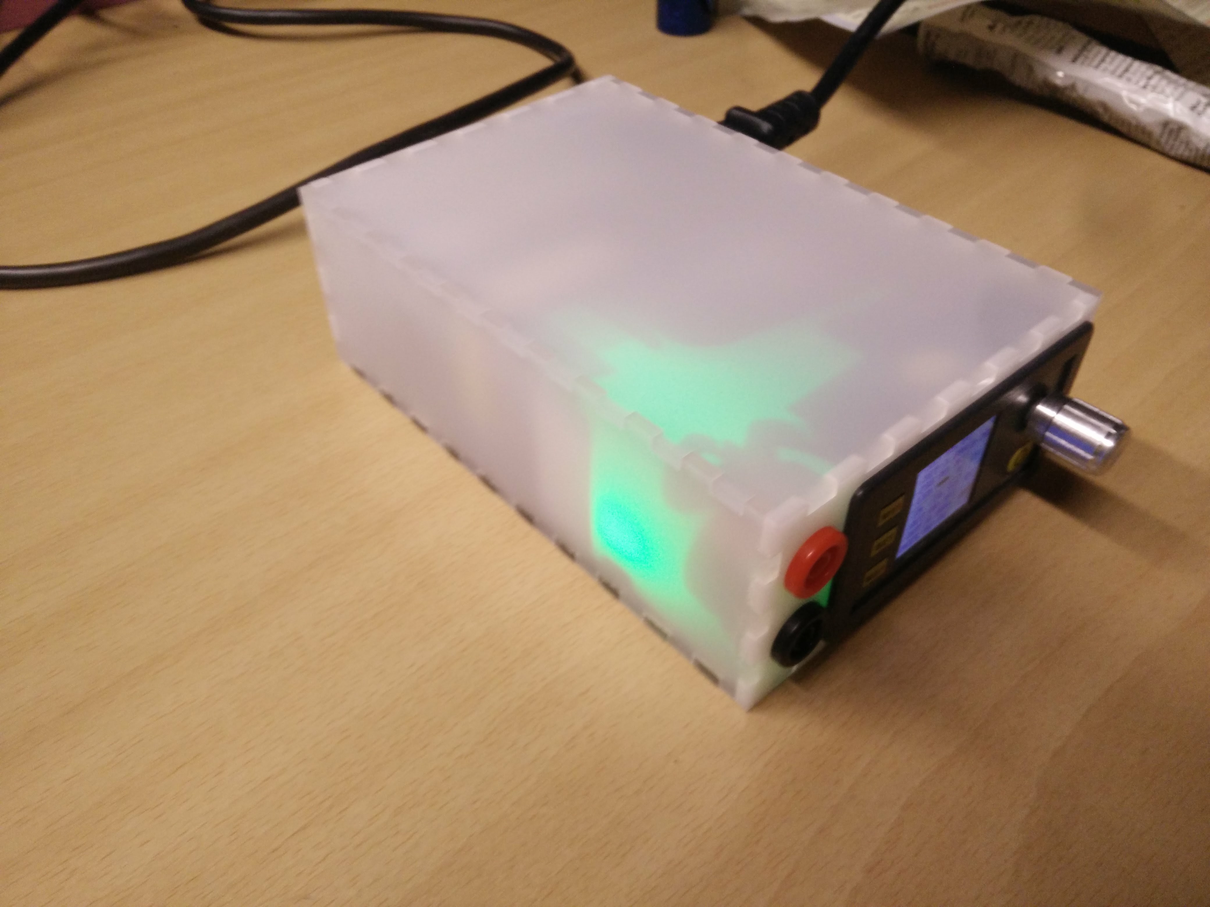
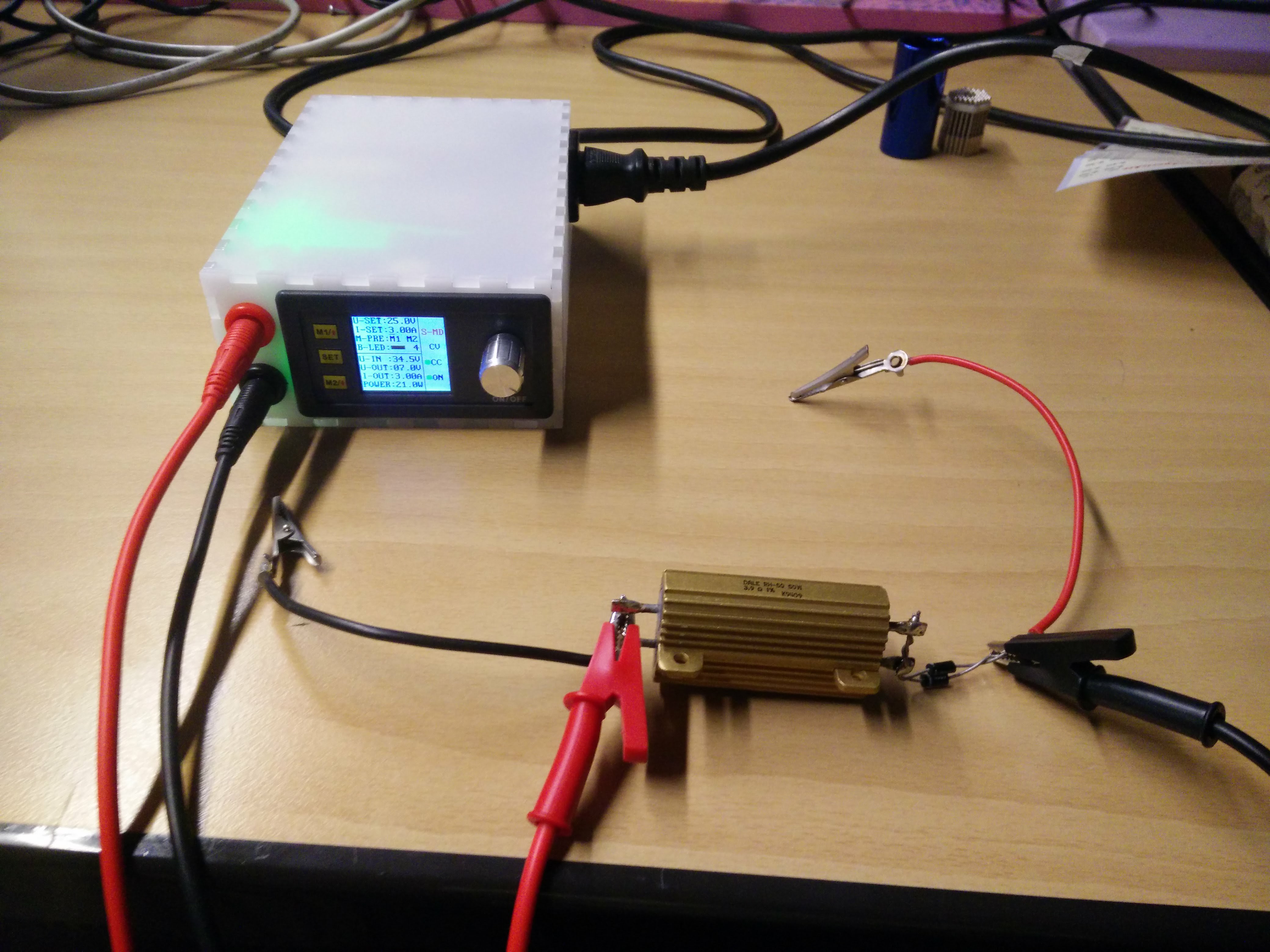
everything falls into place:

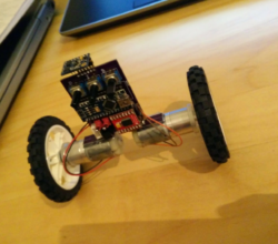
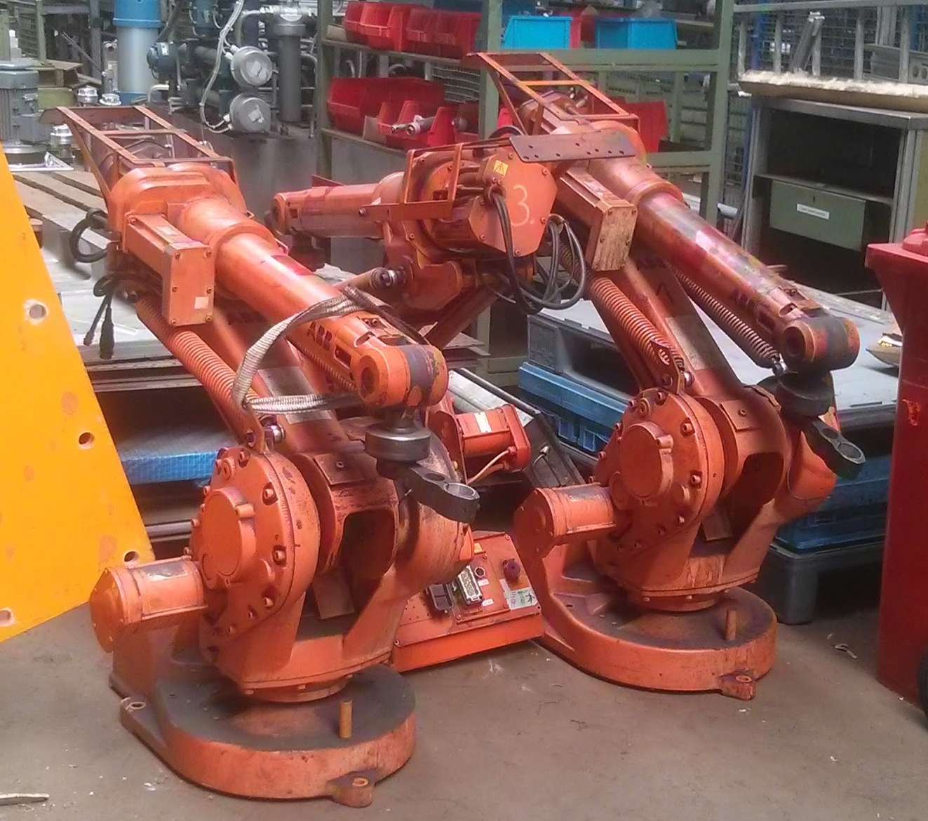
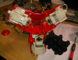
ABB robot retrofit:
Quick and dirty conversion (Marius is a genius) during the LinuxCNC meet 2015 – with some groundwork of mine (getting curcuit plans, “some” probing, …).

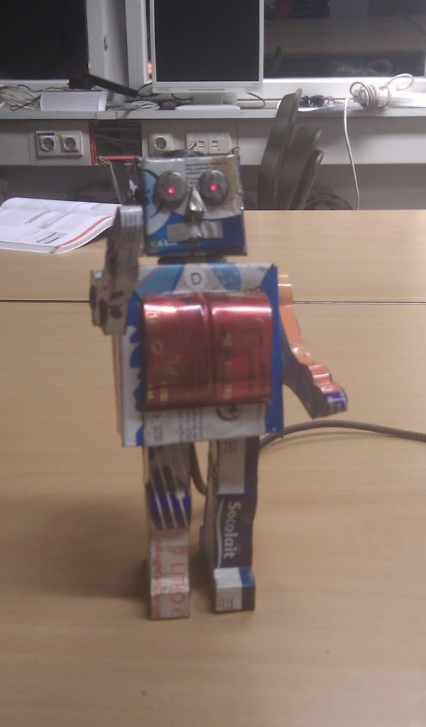
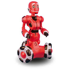
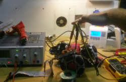
Tribot:
I stumbled upon this little guy somewhere on ebay Kleinanzeigen (~Craigslist) and could not not-buy it.
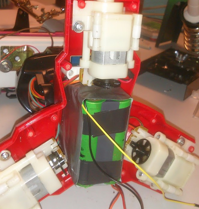
Me (electronics) and two friends (software) hacked it to a Raspberry Pi.
that oughta be enough place for some 18650’s …

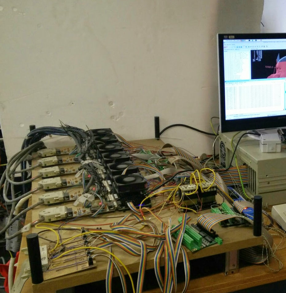
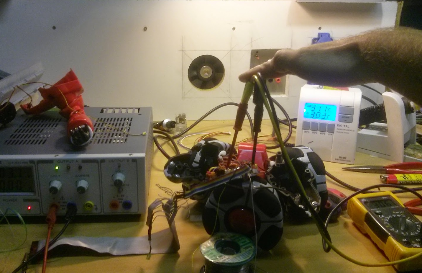
probing for the sensors, motor control
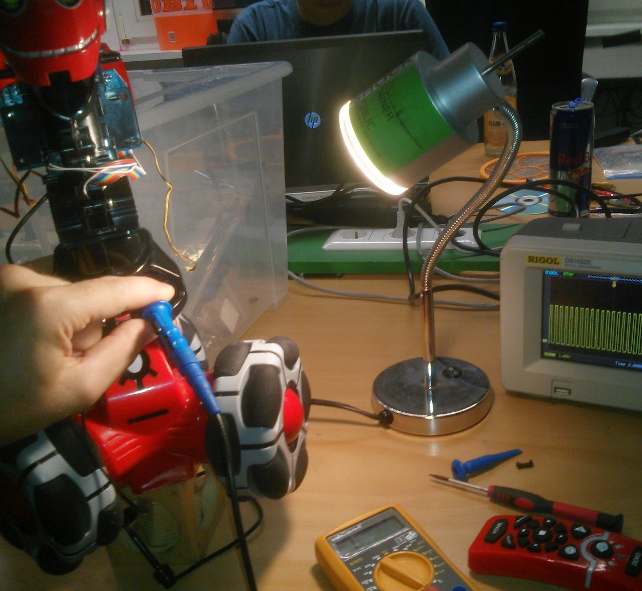
everything hooked up
the biggest of the robots (R3) @shackspace
R3 smashing a screen with a big hammer
<insert video>