poor mans displaywall – 20 screens , 10 gpus and a single computer – part 1

So I’m already way behind documenting again … as always 😉

Since I’m fed up with not getting my name associated with my articles/projects @shackspace I will reduce my projects/commintment towards shackspace/writing for the shackspace’s blog and focus on more on getting my stuff done and just publish on my blog.

It seems I’m the first person on _the internetz_ to attach more than 16 screens to a single computer. *wohoo*

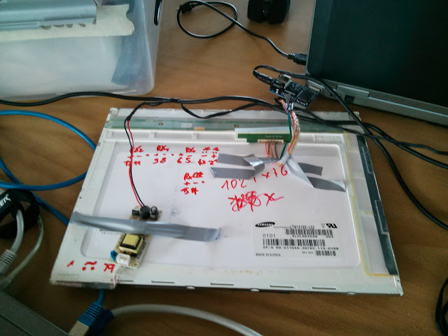
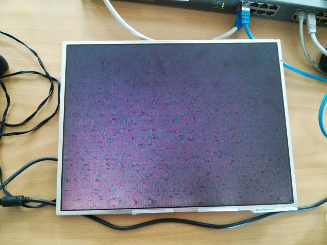
This project began when h0uz3 told me about having 2 pallets of broken Samsung 940B screens in his attic – 26 to be precise.

I was preparing for giving a workshop on repairing said monitors (ordering bags of elkos and fuses) on  planned obsolescence on 26.05. but ended up planning and establishing Repaircafe @shackspace with Dirk instead. People brought enough electric stuff to fix so I just didn’t take care about the monitors and just helped were I could.

I’ll write a separate article on how to fix those 940B’s/lcd’s in general.

With the 26 dead monitors in mind – I thought I could fix at least 20. Getting those on a wall and finding a means of driving them posed challenge enough to just do it.
The goal was to build a poor mans video wall – and I thought it could be done finding the cheapest 5x PCI-E X16 motherboard available + 5 aged dual-gpu, dual head nvidia graphics cards.

I didn’t even know before buying that the graphics cards had 2 separate gpu’s (though 2 minutes on google would have told me) – but I just ordered a pack.
Next up I found the Asrock X79 Extreme 7 that looked like it could do what I wanted to achieve.

^^ never was I so wrong. Freaking SucksASSrock. Never again will I buy an ASSrock board … anything.

The first time my brand new mainboard went up in smoke because of a bent CPU pin.
I got lucky and the CPU didn’t die along with it.

I waited for the replacement part for a few weeks and tried getting all the
graphics cards to work trying multiple OS‘.

I found out the hard way that there’s an obstacle getting more than 8 gpu’s to run in a system.
You wouldn’t expect that and you wouldn’t come across this problem unless you tried.

Also there seems to be a problem for a lot of bios‘ out running into a 32 bit addressing
problem having so many gpu’s.
That didn’t affect my ASRock > X79 Extreme7’s bios though.

So I tried Windows 7 first – because of my good experience regarding multi-screen setups
in Windows OS‘ over the years – but it will only make 8 gpu’s available. The rest
shows up with an exclamation mark in system manager.

You can disable a working gpu and will get a different working (thus assuring there are no
hardware defects).

Next up I gave Windows 8 a quick spin – which imho is an abomination, but let’s not speak
of that here – and it showed no improvements over Win 7 regarding the 8 gpu limit whatsoever.

I tried the latest ubuntu version – as well as a 9.10 install – since the used graphics cards are already somewhat aged –
but again couldn’t get more than 8 GPU’s running – attaching the 5th (dual gpu) card would
always result in a crashed X server.

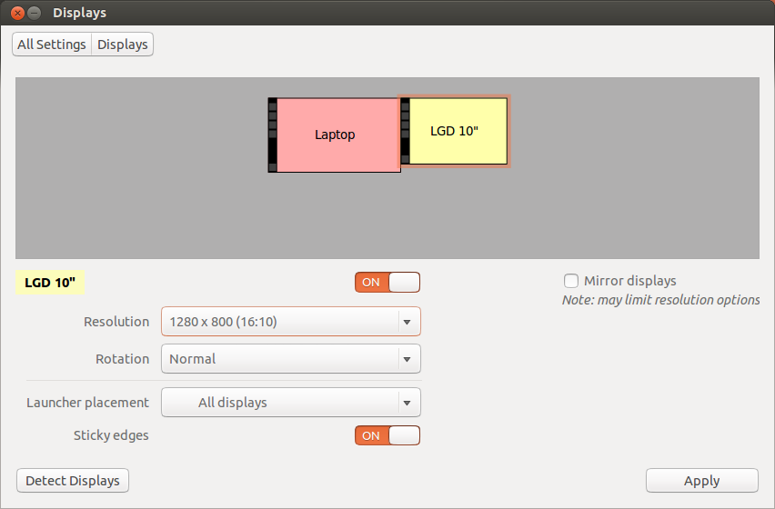
I sucessfully got 16 screens working with the nvidia proprietary driver and my last hope relied
on the nouveau driver (with not too high hopes of success either).

I deinstalled the nvidia proprietary drivers and after an attempted reboot my screens didn’t turn on anymore.

Trying to figure out the cause I came to the conclusion that either the mainboard or
the horribly expensive i7-3930 were to blame.
Since no one I know had either a socket 2011 board nor a CPU I got stuck again.

Last weekend I sat down enjoying momo and Jules half day at a time writing the xorg.conf
by hand (and let me assure you it’s a lot of work keeping track of the 10 different gpu identifiers as
well ass the dualhead ones whilest they keep changing with every added graphics card)

Ubuntu auf dem Nexus 4

Makefu hat auf sein altes (wie kurzlebig doch Handys sind) Nexus 4 Ubuntu geworfen.
Ich bin gespannt auf den Erfahrungsbericht in ein paar Wochen 😉

Jedenfalls muss man im Moment ein Radio Rom Downgrade fahren wenn man unter Ubuntu das wlan zum funktionieren überreden möchte.

Howto:

$ wget https://dl.google.com/dl/android/aosp/occam-jwr66y-factory-74b1deab.tgz
$ tar xvfz occam-jwr66y-factory-74b1deab.tgz
$ adb reboot bootloader
$ fastboot flash radio flash occam-jwr66y/radio-mako-m9615a-cefwmazm-2.0.1700.84.img

cleanup

$ rm  rm occam-jwr66y-factory-74b1deab.tgz 
$ rm -rf occam-jwr66y/

Netzwerk-Durchsatz messen mit iperf (OpenWrt router <-> Linux / Windows wlan)

Auf OpenWrt haben makefu und ich schon USB-over-wlanInstacam und one button realisiert und erst kürzlich einen workshop zum hardware hacking unseres Lieblings-OpenWrt Geräts wr703 (auch bekannt als minikrebs) gegeben. Ich habe OpenWrt auf einem TP-Link WDR4300 sowohl zu Hause – als auch neuestens in der Arbeit am Laufen und kann das Gerät nur wärmstens empfehlen.

Weil ich öfter zu faul bin ein Kabel zum Backup des Laptops auf ein NAS anzuschließen und es über wlan noch nicht so schnell geht wie ich das gerne hätte habe ich gerade eine Intel 633anhmw  N6300 wireless karte (half-size mini pci-express) mit angeblich 450 MBit besorgt und muss jetzt natürlich kurz den Durchsatzgewinn (hoffentlich!) gegenüber der aktuell eingesetzten Atheros AR928X messen.

Dazu verwende ich iperf wie folgt:

Installation von iperf auf der OpenWrt box:

# opkg install iperf

Starten des iperf Servers:

# iperf -s
------------------------------------------------------------
Server listening on TCP port 5001
TCP window size: 85.3 KByte (default)
------------------------------------------------------------

Installation von iperf auf der Ubuntu Mühle:

$ sudo apt-get install iperf

Benchmark starten:

$ iperf -c

In diesem Falle die OpenWrt box

$ iperf -P5 -f M -c 192.168.1.1

^^ die Parameter findet man mit „iperf -h“ oder siehe weiter unten. Ergebnis von Qualcomm Atheros AR928X [168c:002a]:

[ 3] 0.0-10.1 sec 36.1 MBytes 3.59 MBytes/sec

Intel Corporation Centrino Ultimate-N 6300 [8086:422b] sucks ass

[ 5] 0.0-10.5 sec 4.50 MBytes 0.43 MBytes/sec

^^ na da habe ich mir ja was großartiges gegönnt …

Und der Gewinner ist: Centrino(R) Ultimate-N 6300 AGN – die alte Karte aus meinem Notebook, die ich in Nadia’s Windows Laptop gesteckt habe, damit Sie auch 5GHz hat 😉
Da fällt mir auch ein, warum ich die Atheros Karte gekauft habe … weil die Intel Karten nach meiner Erfahrung (2200gb 2915abg, 6300n, jetzt: 633anhmw) in Linux einfach immer nur Ärger machen. So auch in diesem Fall wieder.

[  3]  0.0-10.0 sec  88.4 MBytes  8.82 MBytes/sec

LAN ist besser … und wohl begrenzt durch IO auf dem OpenWrt Router … ich teste das gleich noch zum NAS

[ 3] 0.0-10.0 sec 316 MBytes 31.6 MBytes/sec

… und siehe da … zum NAS über den wdr4300

[ 3] 0.0-10.0 sec 1084 MBytes 108 MBytes/sec

Nachtrag: Mit Kernel 3.13. bin ich jetzt immerhin bei

[  3]  0.0-10.0 sec  74.2 MBytes  7.40 MBytes/sec

Nachtrag: Intel 7260 HMWB (702.11ac) (wartet noch auf den passenden AC wlan Router)

[  3]  0.0-10.0 sec  91.0 MBytes  9.06 MBytes/sec

Iperf Parameter:

$ iperf -h
Usage: iperf [-s|-c host] [options]
       iperf [-h|--help] [-v|--version]

Client/Server:
  -f, --format    [kmKM]   format to report: Kbits, Mbits, KBytes, MBytes
  -i, --interval  #        seconds between periodic bandwidth reports
  -l, --len       #[KM]    length of buffer to read or write (default 8 KB)
  -m, --print_mss          print TCP maximum segment size (MTU - TCP/IP header)
  -o, --output    <filename> output the report or error message to this specified file
  -p, --port      #        server port to listen on/connect to
  -u, --udp                use UDP rather than TCP
  -w, --window    #[KM]    TCP window size (socket buffer size)
  -B, --bind      <host>   bind to <host>, an interface or multicast address
  -C, --compatibility      for use with older versions does not sent extra msgs
  -M, --mss       #        set TCP maximum segment size (MTU - 40 bytes)
  -N, --nodelay            set TCP no delay, disabling Nagle's Algorithm
  -V, --IPv6Version        Set the domain to IPv6

Server specific:
  -s, --server             run in server mode
  -U, --single_udp         run in single threaded UDP mode
  -D, --daemon             run the server as a daemon

Client specific:
  -b, --bandwidth #[KM]    for UDP, bandwidth to send at in bits/sec
                           (default 1 Mbit/sec, implies -u)
  -c, --client    <host>   run in client mode, connecting to <host>
  -d, --dualtest           Do a bidirectional test simultaneously
  -n, --num       #[KM]    number of bytes to transmit (instead of -t)
  -r, --tradeoff           Do a bidirectional test individually
  -t, --time      #        time in seconds to transmit for (default 10 secs)
  -F, --fileinput <name>   input the data to be transmitted from a file
  -I, --stdin              input the data to be transmitted from stdin
  -L, --listenport #       port to receive bidirectional tests back on
  -P, --parallel  #        number of parallel client threads to run
  -T, --ttl       #        time-to-live, for multicast (default 1)
  -Z, --linux-congestion <algo>  set TCP congestion control algorithm (Linux only)

Miscellaneous:
  -x, --reportexclude [CDMSV]   exclude C(connection) D(data) M(multicast) S(settings) V(server) reports
  -y, --reportstyle C      report as a Comma-Separated Values
  -h, --help               print this message and quit
  -v, --version            print version information and quit

[KM] Indicates options that support a K or M suffix for kilo- or mega-

The TCP window size option can be set by the environment variable
TCP_WINDOW_SIZE. Most other options can be set by an environment variable
IPERF_<long option name>, such as IPERF_BANDWIDTH.

Report bugs to <iperf-users@lists.sourceforge.net>


Fahrradfelge einspeichen

Ein Kumpel von mir brauchte unbedingt!, diese Eine, spezielle Nabe in seinem grünen Bismark (vintage Fahrrad um nicht zu sagen Schrottrad).

Na gut. Du wolltest doch schon-immer-mal eine Felge eingespeicht haben …

Um das ganze Unterfangen unnötig zu komplizieren waren natürlich die vorhandenen Speichen die falsche Länge (durch den gescheiterten Einspeichversuch eines Dritten).

Aufgefallen ist mir das dann als ich das Rad quasi komplett eingespeicht hatte. Dass dir das nicht passiert – nimm diesen Rechner hier.

Zum Einspeichen selbst habe ich mich an der Anleitung von der gleichen Seite orientiert, zusätzlich hat mich Georg von Fahrräder für Afrika fachmännisch angeleitet.

Impressionen:


Natürlich hat Max dann das Rad den Tag danach gleich wieder zerlegt (wie er mir einige Monate später beichtete), beim Missglückten Bremsmanöver und folgendem Überschlag. Shit happens.

Für die Zukunft: Nein, ich kann keine Felgen einspeichen! (it sucks donkeyballs)

K2 Kick Pro Kickboard mod with 3kw outrunner

I still have a backlock of the past two years – but with this project I actually did quite a nice job documenting it.

Best of all it’s

and you can get all the CAD files on github.

Now to the build. Since I’m not big on baking cookies for Christmas – I invested my time in a project I was thinking about doing for some time: Building an electrified kickboard. This is the result:

The ingredients are:

from the shop:

from the parts bin:

cooking:

  • a day of CAD work
  • a day of milling aluminum (and some minutes on a lathe)
  • a day putting it all together + some soldering

I took the easy way – just to get the thing functioning (let’s deal with a microcontroller + programming later – if I need to) – and just soldered an extension cord + push potentiometer to the servo tester.

Also I desoldered everything unneeded from the servotester – but the better/faster method would have been just to cut the unneeded parts with pliers.

Next I sat down at the computer and let my ideas form in CAD. (This is the 3rd iteration)

First milled parts taking shape (these are the right and left axle mounts)


There is a mechanism for tensioning the belt by sliding the motor mount.


It looks nice enough … doesn’t hold up to the torque though – and so I had to redesign it later.


The process of milling the back plate:

The program used (XpertMILL):

and the finished part next to the original one:


The „gas pedal“ fitted to the handle:

A video of the first motor test:

As a quick hack to get moving I made a big Y-cable to fit the batteries into the left and right trouser pocket with a really long cable down to the esc.

A test ride (video suffering from vvs)

She is having trouble keeping the front wheels on the ground during acceleration 😉

The process of building the new battery pack from used Makita battery packs with 18650 cells:

balancing the Frankenstein pack:

Lasercut insulator rings and leads soldered across the top (3p configuration)

Soldered into a 7s 3p pack:

shrink wrapped:

Fitted to the kickboard:

For safety I should still put a 2mm aluminum sheet under the cells.

Some links and data:

Quite useful for calculating the drive train is http://smarthost.maedler.de/maedlertools/maedler.html

The data:

The measured no load rpm of the motor is 1295 which according to 4.2V*6*170rpm/V *12 / 40 = 1285 rpm … sounds legit.

This yields in 1295U/min * 11cm * pi / 100 cm/m / 1000 m/km * 60 min/h = 26.85 km/h @ no-load … or estimated 26.85 km/h * 0.8 = 21.5 km/h – theoretical.

The top speed – measured – is 22km/h with 6S, or 26km/h with 7S.

Energy consumption is about 13Wh/km (gunning it).

The battery pack holds 3.7V*3*7*2.5Ah=194.25Wh nominal … but since these are used and abused cells from Makita power drills the actual value should be lower.

Theoretical range is therefore about 15km – the real range is yet to be tested.

Max load was 38A – that would be 1kw of power to the motor – with a 100kg person on it and I guess the limiting factor are the cells and worn down T5 belt that will be replaced with an AT5 belt and pulleys.

http://www.youtube.com/watch?v=Wa9pRsZ2JA4

battery charge magnets

Sometimes you happen to run across a power source without tabs – especially when playing with used/reconfiguring e.g. 18650 cells.

I built these „charge magnets“ from 6x2mm ring magnets with 2mm hole and 1x6mm end sleeves.
It needed three different sizes to empirically determine the right size so the end sleeve would fit.


The electrical contact is quite good:

Yeah, I know, these aren’t NiMh…

Does this count as art?

Can also be used to get power sth out of the batteries.

capacitive spot welder

So that one evening me and Samu decided to build a capacitive spot welder from scraps.

safety first (in case the caps blow up on fast discharge aka shorting).


A nice audio transformer


The resistors are to limit the current for charging.

Pulse duration and stuff was done on a Jockiboard and as high amp drivers we used some (maybe 3 in parallel) mosfets (hexfets) from old motherboards.

Some testing:


(thin metal)


(tea light aluminum cups)

We never got around to  finishing the spot welder … but who knows maybe someday.


OpenWrt -> Linksys wag160n_v1

Victory: one of my tiny white whales has been slain.

Flashing OpenWrt to your router is easy as pie – at least in some cases – in other only if you know what you’re doing and a suitable firmware file is available.
I have to admit it took me almost 2 years to get OpenWrt on my Linksys wag160n v1.
Today I conquered that tiny white whale of mine.

serial connection soldered

I bought the unit back in 2011 because it seemed like a good choice looking at the OpenWrt toh (supported hardware) – at the time.

After I got it I quickly soldered the serial connector to the board and dumped the configuration data for the ath chip as described in the OpenWrt wiki.

After that it took me quite some time trying to build my own firmware – incorporating all the patches which should yield in a usable firwmare.

I got that done enduring some pain (a few days of forcing myself to patching files and compiling the firmware).

So there I was with the untested firmware file that still wouldn’t upload through the webinterface of my Linksys router.

Frustrated I threw the unit into it’s box and then some corner.

While moving the box hit the light of day again so I saw myself forced to either conquer the box or throw it in the trash.

Today I managed to get it done – and here is how that works:

You need to get a tftp server up and running (I’m running some Ubuntu).

sudo apt-get install tftpd-hpa tftp

Be sure to test the setup – put some file in /var/lib/tftpboot  e.g.

sudo sh -c 'echo "hallo" > /var/lib/tftpboot/test'

tftp localhost
 get test
 Received 7 bytes in 0.0 seconds

So now you’re sure your tftp server works.

You can get the firmware for the wag160n v1 (Attitude Adjustment, r34073) here which is built by Virus or try the related wag160n_v1 forum thread.

Copy your downloaded/built openwrt image to to /var/lib/tftpboot


sudo cp openwrt-WAG160Nv1-squashfs-cfe-attitude-adjustment-beta-2.bin /var/lib/tftpboot/bcm963xx_fs_kernel

That file (and the name needs to be bcm963xx_fs_kernel because that’s the IP the wag160n CFE expects) is now waiting there to get pulled by your router.

Connect to your router with an ethernet cable.
Assign 192.168.1.100 to your box – because that’s what the wag160n will try pull the boot image from
(192.168.1.100 as gateway).

Next up you need to connect to the wag160n through telnet.

Setup minicom:

sudo minicom -s

-> serial port setup
A -> /dev/ttyUSB0 (or dev/ttyACM0 or whatever)
E -> E (115200) -> Q (8N1)
-> safe setup as dfl (or as <configuration_name>)

and connect with:

sudo minicom

or if you saved a named config with:


sudo minicom <configuration_name>

You should now be presented with a boot screen after plugging the power supply into the wag160n.

Wait for:

*** Press any key to stop auto run (1 seconds) ***

And press a key. Now you’re in CFE:

CFE>

press f.

Loading 192.168.1.100:bcm963xx_fs_kernel ...

Finished loading 2752516 bytes

Flashing root file system and kernel at 0xbfc10000: ............................

.
 *** Image flash done *** !
 Resetting board...

And that’s it. Next time you will be greeted by the openwrt screen.

</pre>
BusyBox v1.19.4 (2012-11-04 23:56:37 CET) built-in shell (ash)
Enter 'help' for a list of built-in commands.

_______ ________ __
 | |.-----.-----.-----.| | | |.----.| |_
 | - || _ | -__| || | | || _|| _|
 |_______|| __|_____|__|__||________||__| |____|
 |__| W I R E L E S S F R E E D O M
 -----------------------------------------------------
 ATTITUDE ADJUSTMENT (Attitude Adjustment, r34073)
 -----------------------------------------------------
 * 1/4 oz Vodka Pour all ingredients into mixing
 * 1/4 oz Gin tin with ice, strain into glass.
 * 1/4 oz Amaretto
 * 1/4 oz Triple sec
 * 1/4 oz Peach schnapps
 * 1/4 oz Sour mix
 * 1 splash Cranberry juice
 -----------------------------------------------------

Set a root password through telnet

passwd

and you’re good to connect through ssh.

Another option would be to hexedit the firmware file so you can load it through the Linksys firmware upgrade.
You would still need telnet to the box because ssh is only enabled after setting a root password with the above linked firmware file.

HDMI -> LVDS

„The only difference between screwing around and science is writing it down.“

Na gut. Oder zumindest kann ich später nachschauen wie es geht.

Ich habe mal nachgeschaut, wie man die sich mit der Zeit ansammelnden TFT Displays nutzen könnte und bin dabei u.a. auf den hdmi lvds converter von chalk-elec.com gestoßen.

HDMI_LVDS_back

HDMI_LVDS_front

Diesen habe ich vor ein paar Monaten bestellt – und spontan gestern Nacht verdrahtet.

Damit würde sich u.a. ein Display am Multicopter realisieren lassen. Die Zeit wird es zeigen ob ich die Idee weiterverfolgen und umsetzen werde.

Bestellt habe ich den Adapter als 1920×1080 24bit Version – die programmierten EDID-Informationen sind aber leider falsch – so taucht ein LGD  10″ 1280×800 Display im System auf:

hdmi_lvds_LGD10
$ xrandr
HDMI1 connected 1280x800+1600+0 (normal left inverted right x axis y axis) 217mm x 136mm
1280x800       60.0*+   40.0

Na gut - erst mal schnell an ein herumliegendes Display (Samsung LTN141X8-L02) angekabelt.
Relevant ist dabei eigentlich nur die richtigen Pins miteinander zu verbinden.
Pinout vom Display
Samsung_LTN141X8-L02_pinout
Pinout vom LVDS Adapter:
hdmi_lvds_pinout
Das kam dabei raus:
HDMI_LVDS_cables

Dell_HDMI_LVDS_Samsung_10

Joa, nicht so toll:

HDMI_LVDS_fail

Der Versuch einfach die richtige Auflösung "rauszupusten":

$ xrandr --addmode HDMI1 1024x768

$ xrandr
HDMI1 connected 1024x768+1600+0 (normal left inverted right x axis y axis) 217mm x 136mm
1280x800       60.0 +   40.0
1024x768       60.0*

hdmi_lvds_LGD10_addmode

bringt den Erfolg:

HDMI_LVDS_success

proof of concept: done
Der nächste Schritt wäre einen 27" IPS Monitor zu schlachten und das Experiment zu wiederholen.

Petitionen

Die Entwicklung dass immer mehr Leute einfach ihre Meinung kundtun können – und sei es nur durch einen Klick zur Unterstützung einer Online-Petition ist positiv.

Dass man sich jedoch damit zum Bittsteller degradiert nicht.

Diese duckmäuserische Haltung sich nur innerhalb der vorgegebenen Wege zu bewegen,
die Fügung in die Rolle des ohnmächtigen Untertan lehne ich strikt ab.

Wir sind der Souverän – auch wenn uns diese Verantwortung nicht allzeit bewusst ist.